
Me and lighting.
The duration of this project spanned my middle school and undergraduate years, and with each new location I always wanted to improve the design and implement it.
Beginning
At first, I just wanna make a switching power supply. When I was came across to the NE555 chip, I found the mystery of AC world.
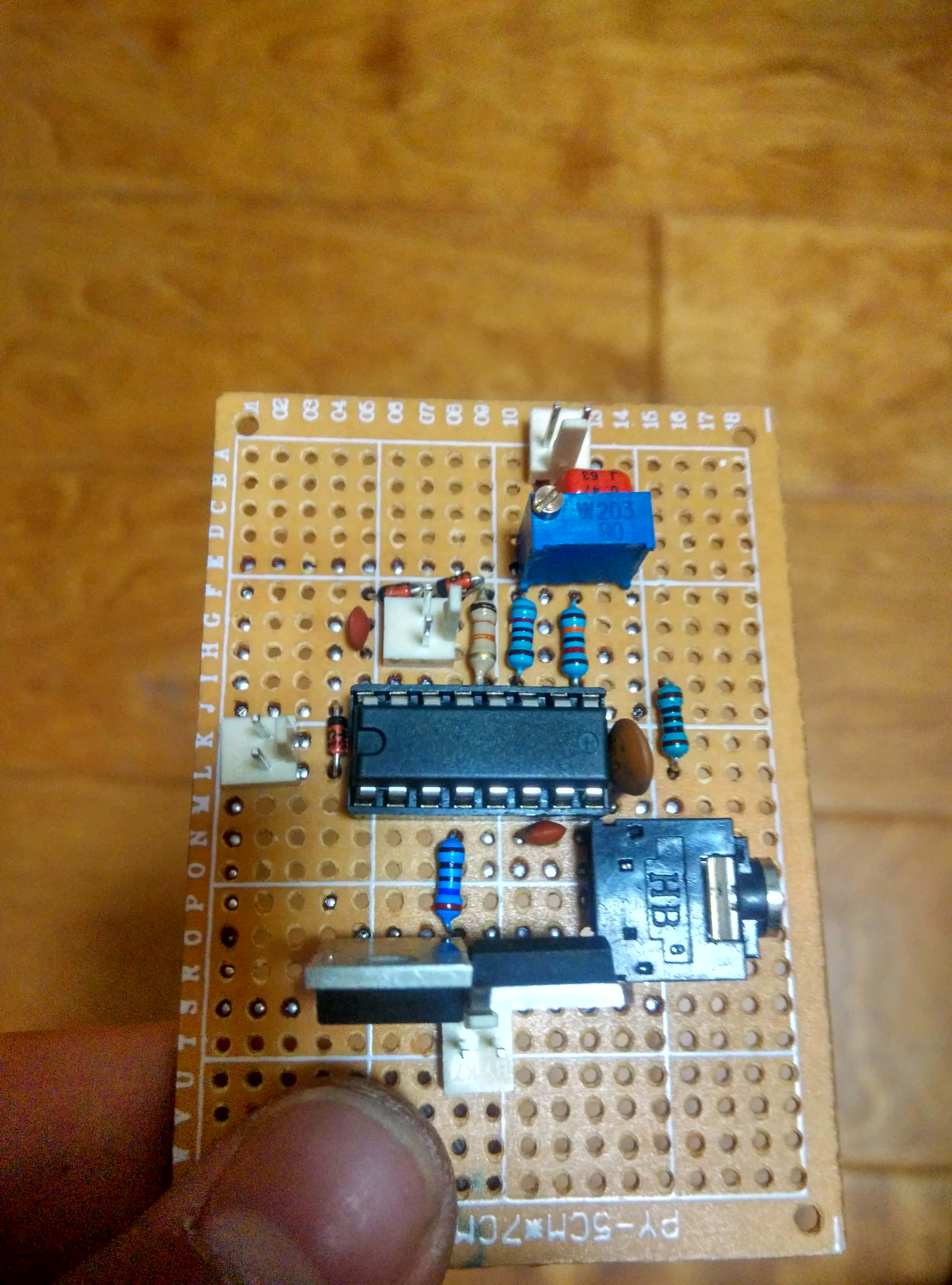
This is a CD4046 based PLL Driver.
So I changed my target and make a inverter. At the same time, I searched a interesting device which could released over 1,000,000 voltages. It was invented by Nicola Tesla.
Of course, the load of my inverter is Tesla Coil. To verified the functions of the coil, my first target is make a SGTC (Spark Gap Tesla Coil).
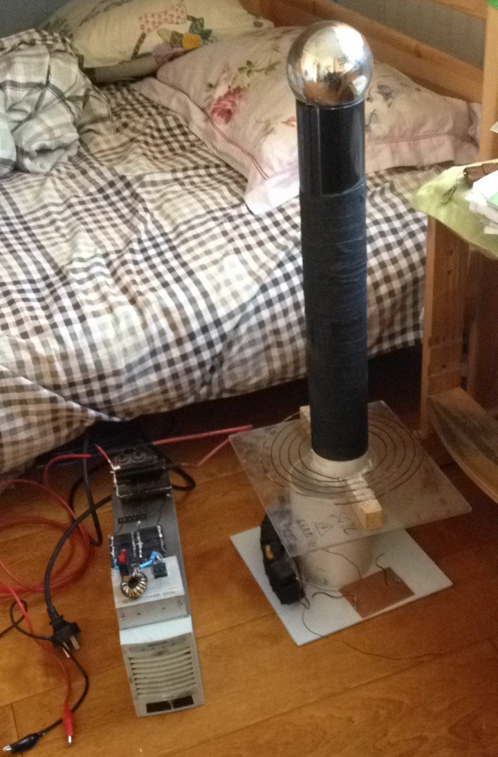
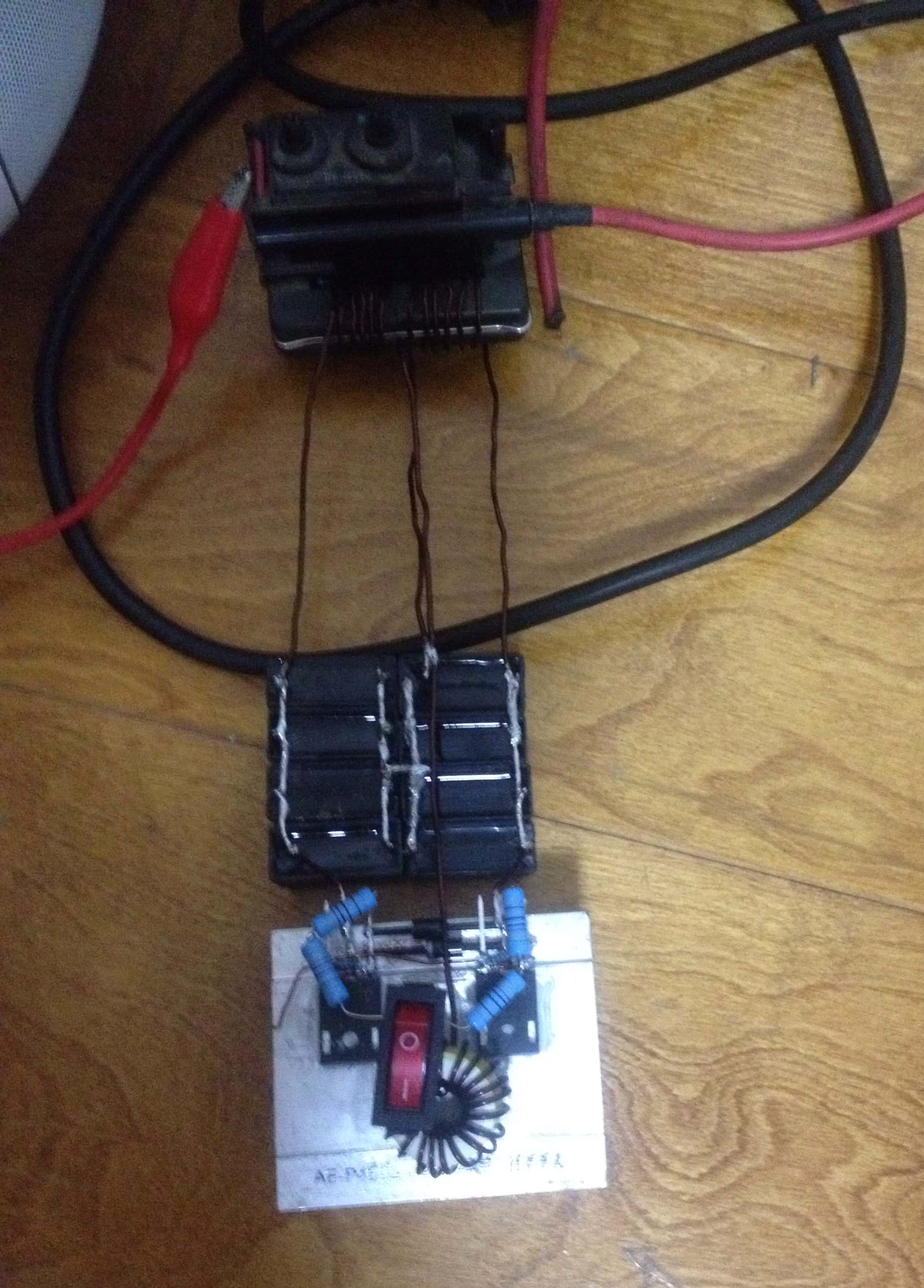
There is a HV generator and a inverter. At that time, I was a junior high school student. So my solution is Classical ZVS inverter + CRT Line output transformer.
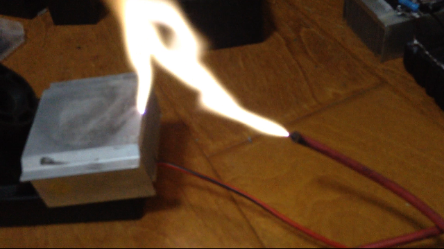
Here are the arc of the output, 15kV DC Apporx.
Gen 1
To replace the spark gap, we need to artificially control the coil with chips and transistors.
All circuit cited from Steve UD1.3
Based 74HC74/74HC08/74HC04
The isolator is HFBT1414/HFBT2412 ST Optical Fiber
The interrupt signal transmitted through Fiber.
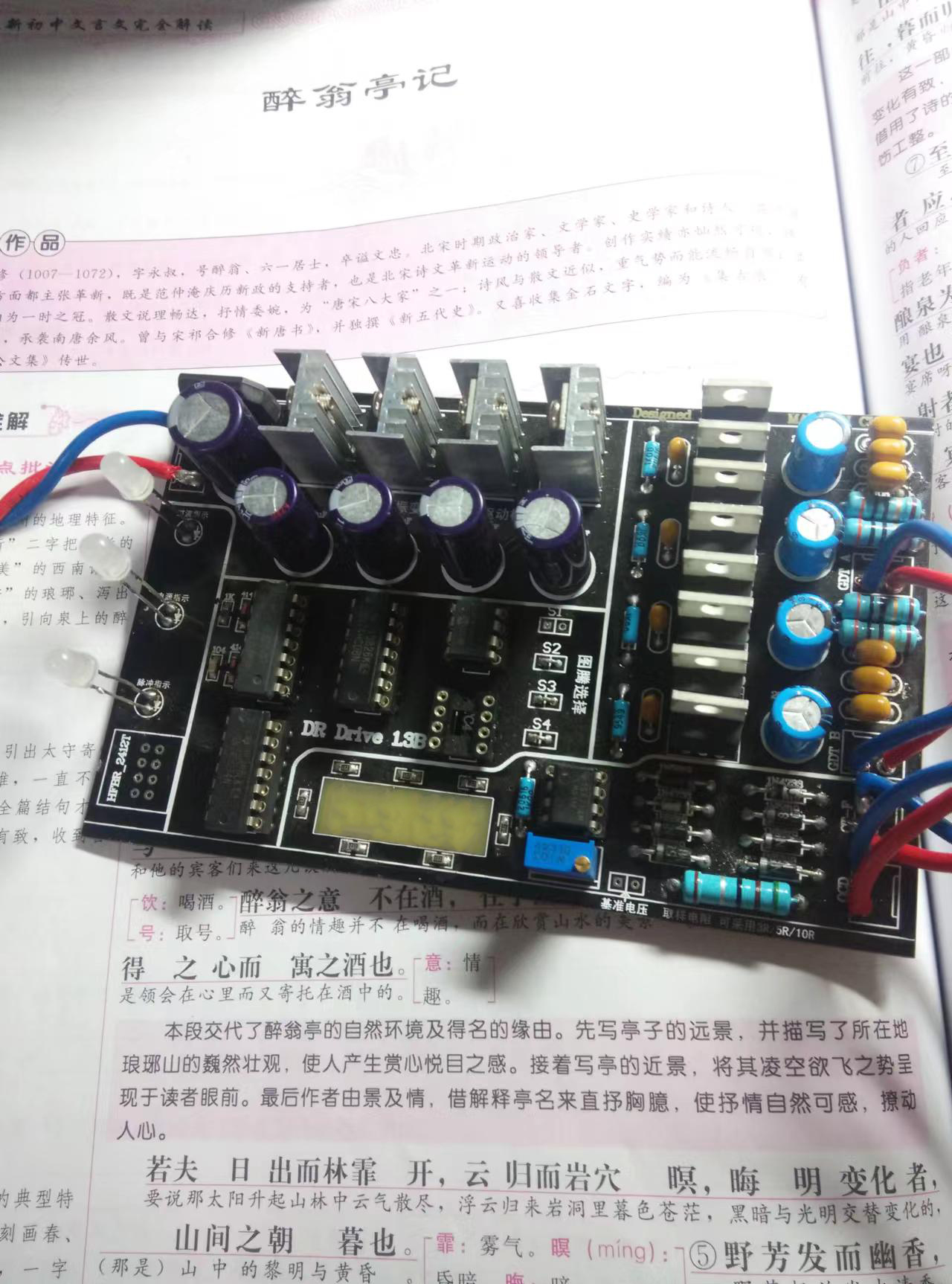
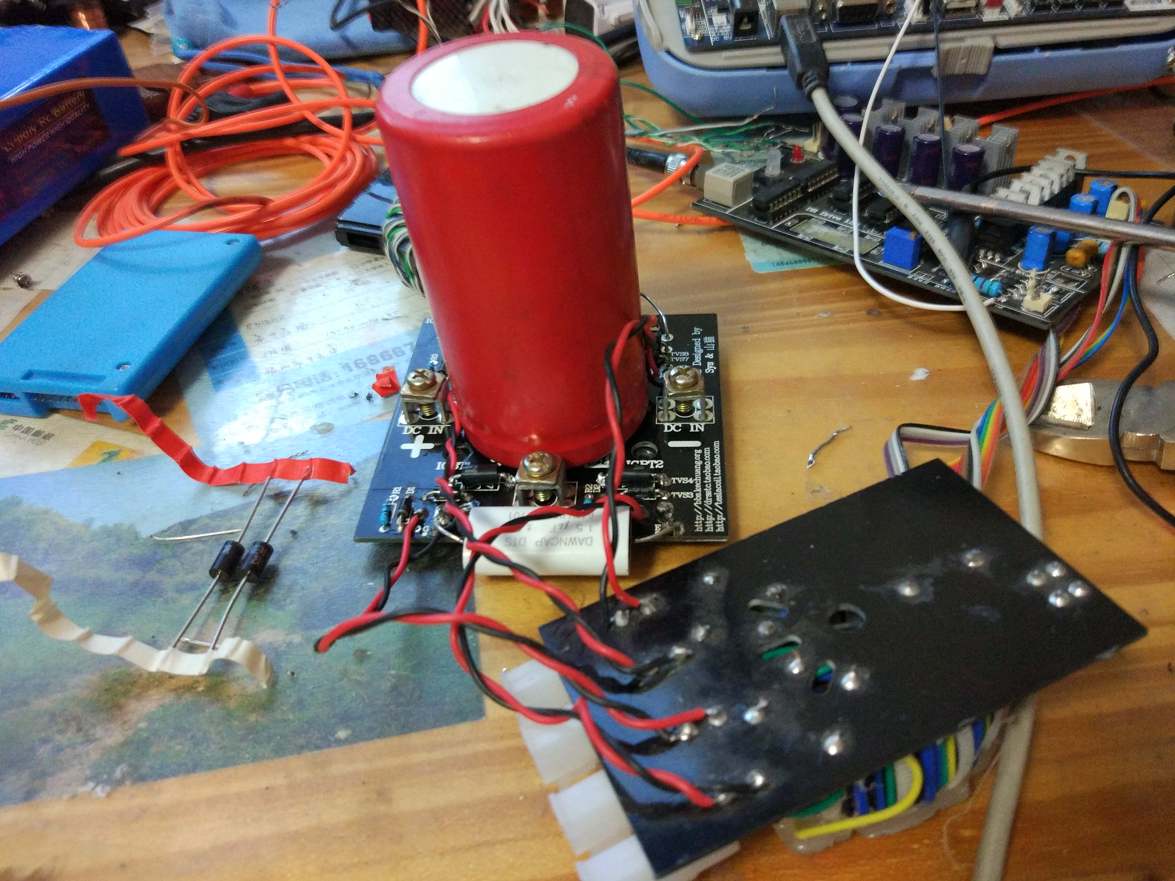
For inverter, I chose full bridge topology. The IGBT driver used magnetical isolatator (GDT, Gate Driver Transformer, made of Ethernet Wire)
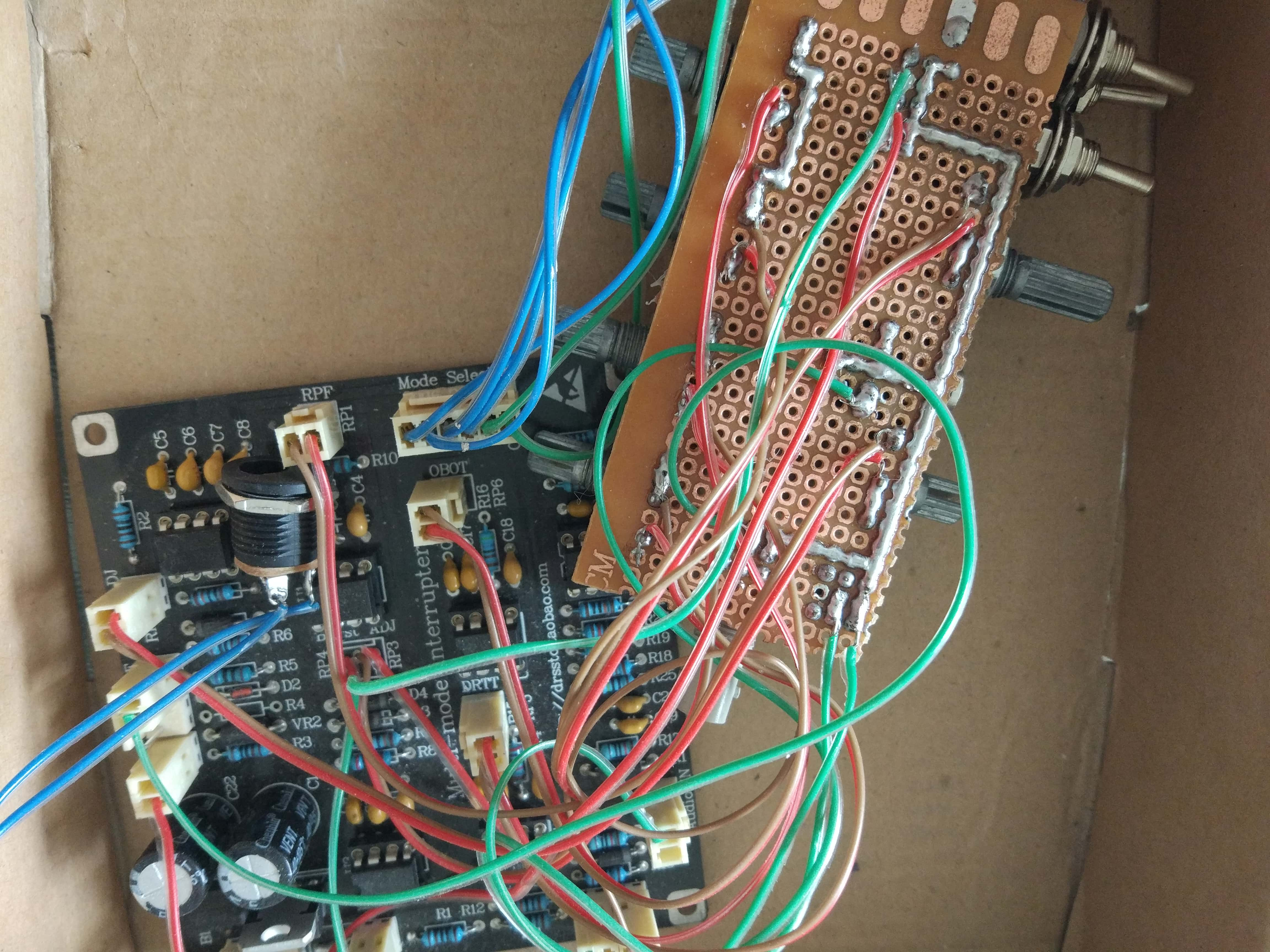
To control the working duration, I designed a interrupt signal generator. It based on NE555 and LM393.
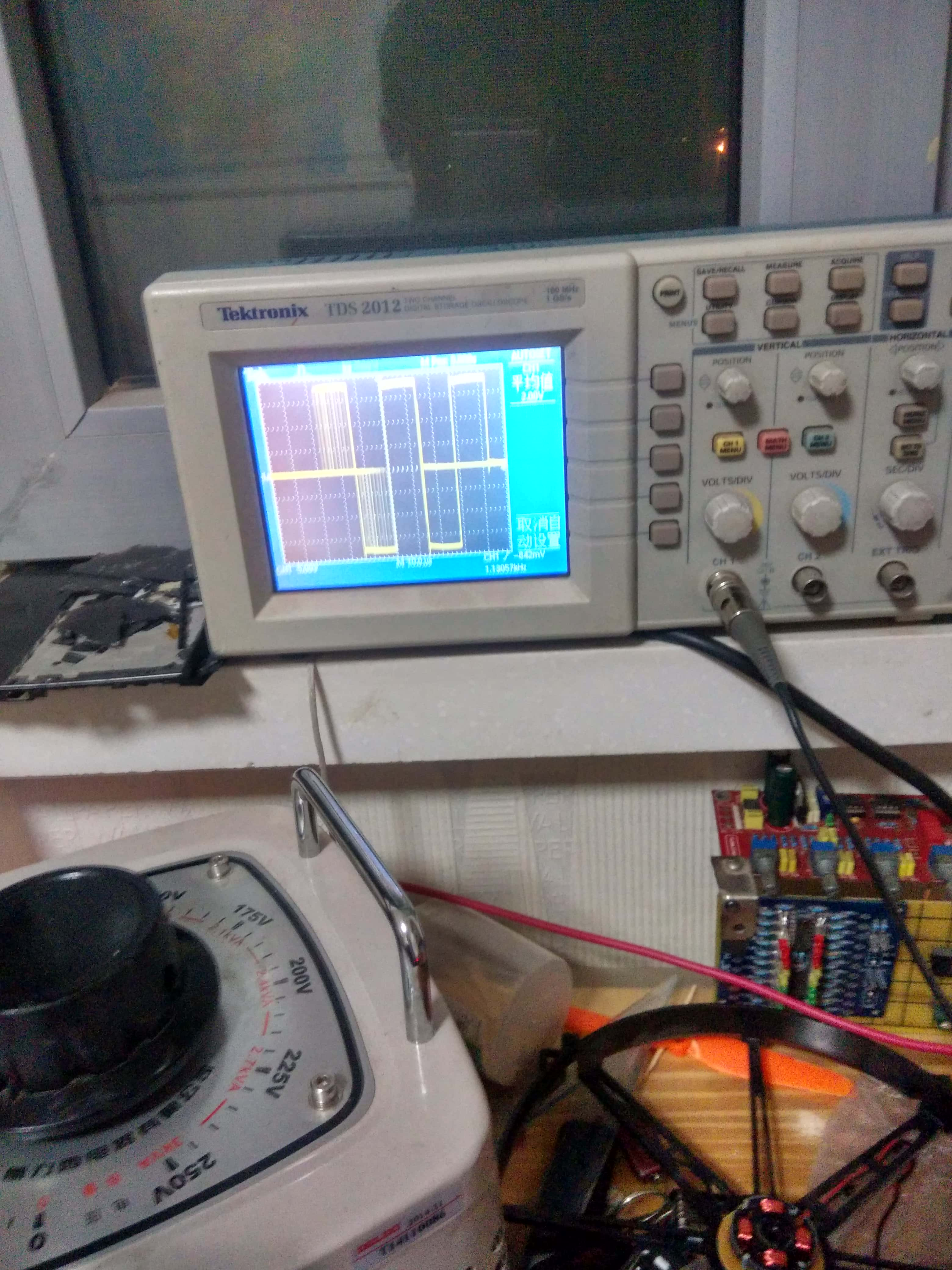
Here are the testing site. The MCU responsible for generating a fake primary working excitation to trig the D trigger.
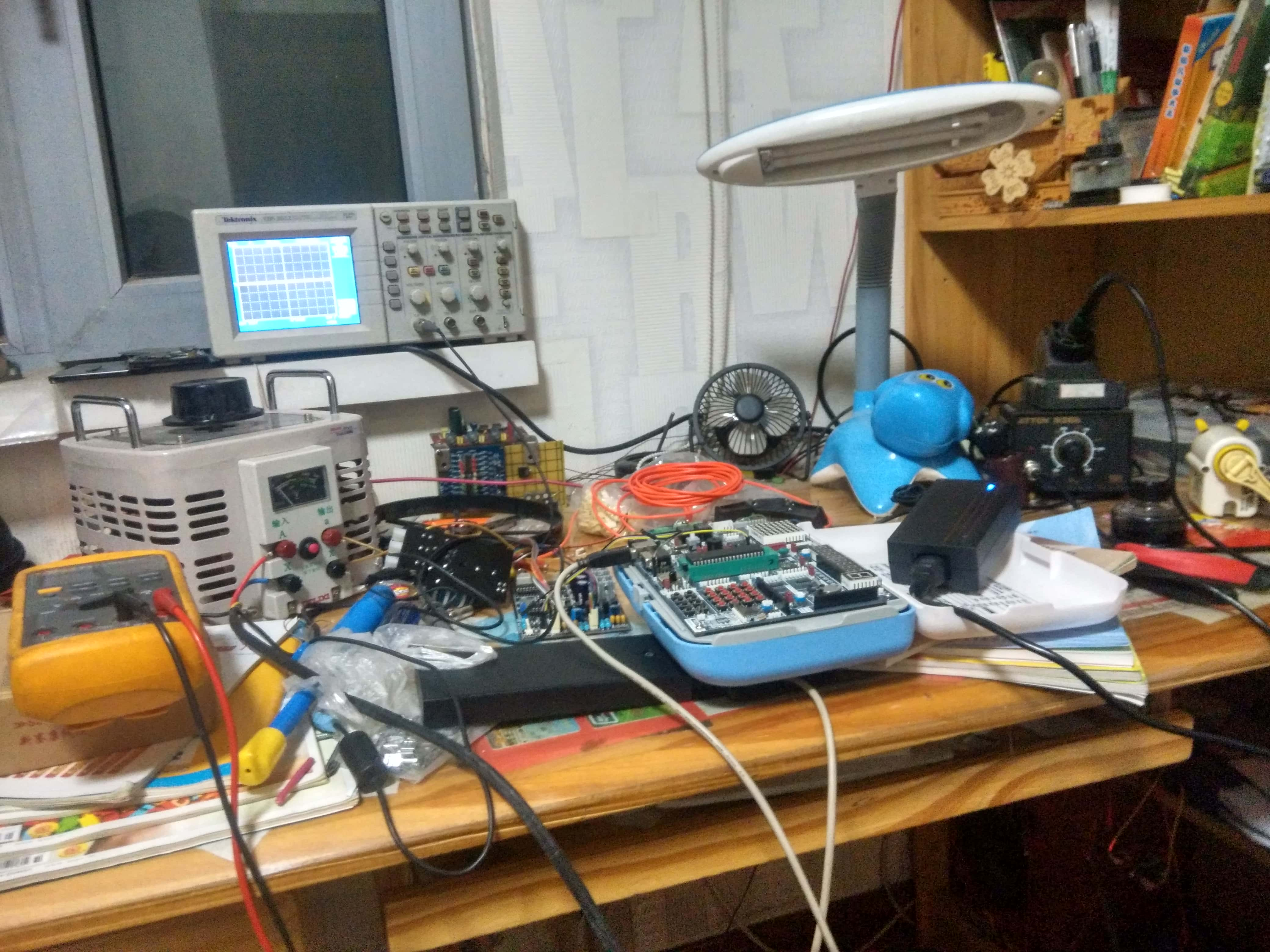
And the oscilloscope result.

This is the current sensor and feedback sensor.
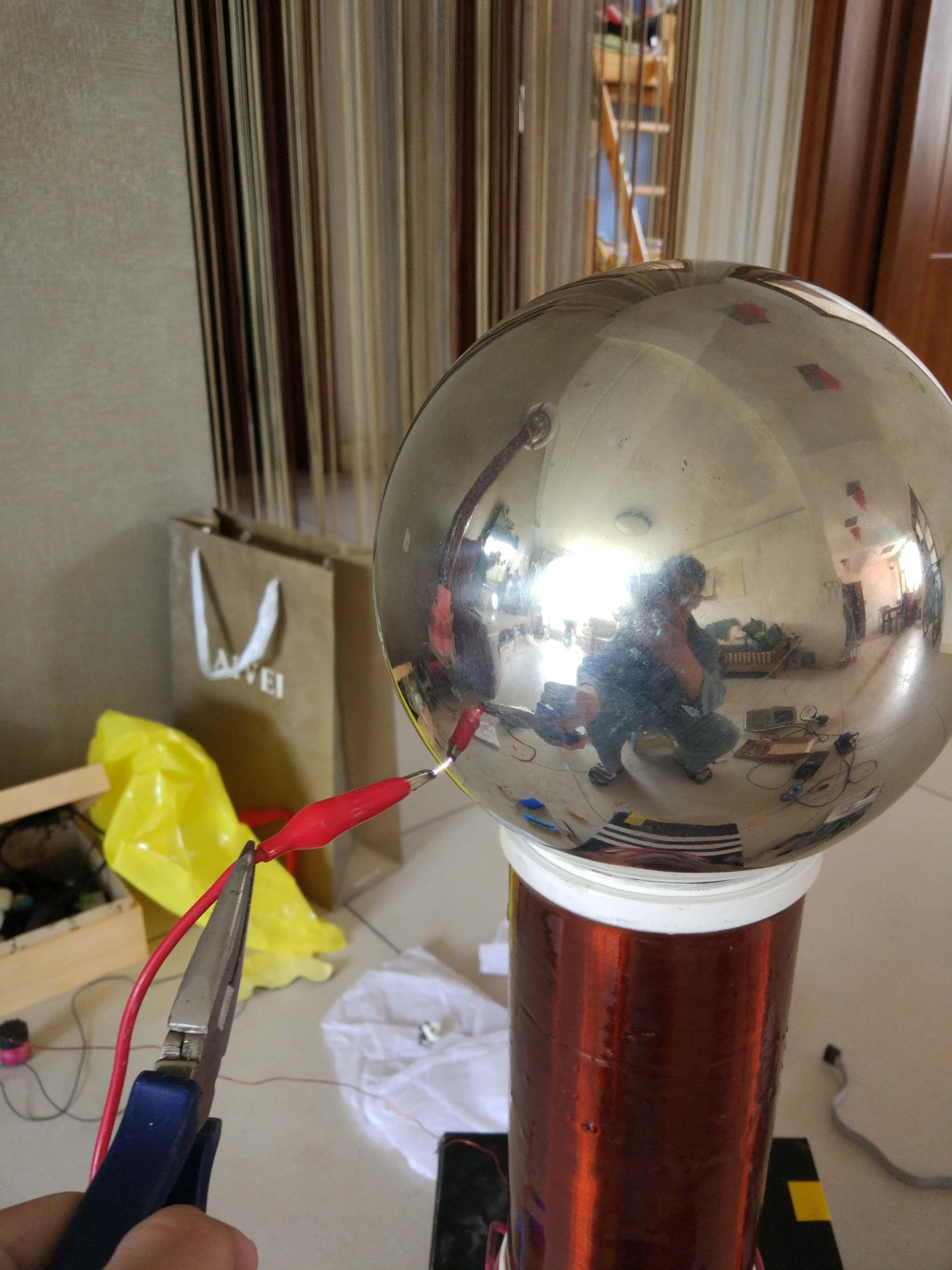
Then I mounted the relevant equipment to the coil.
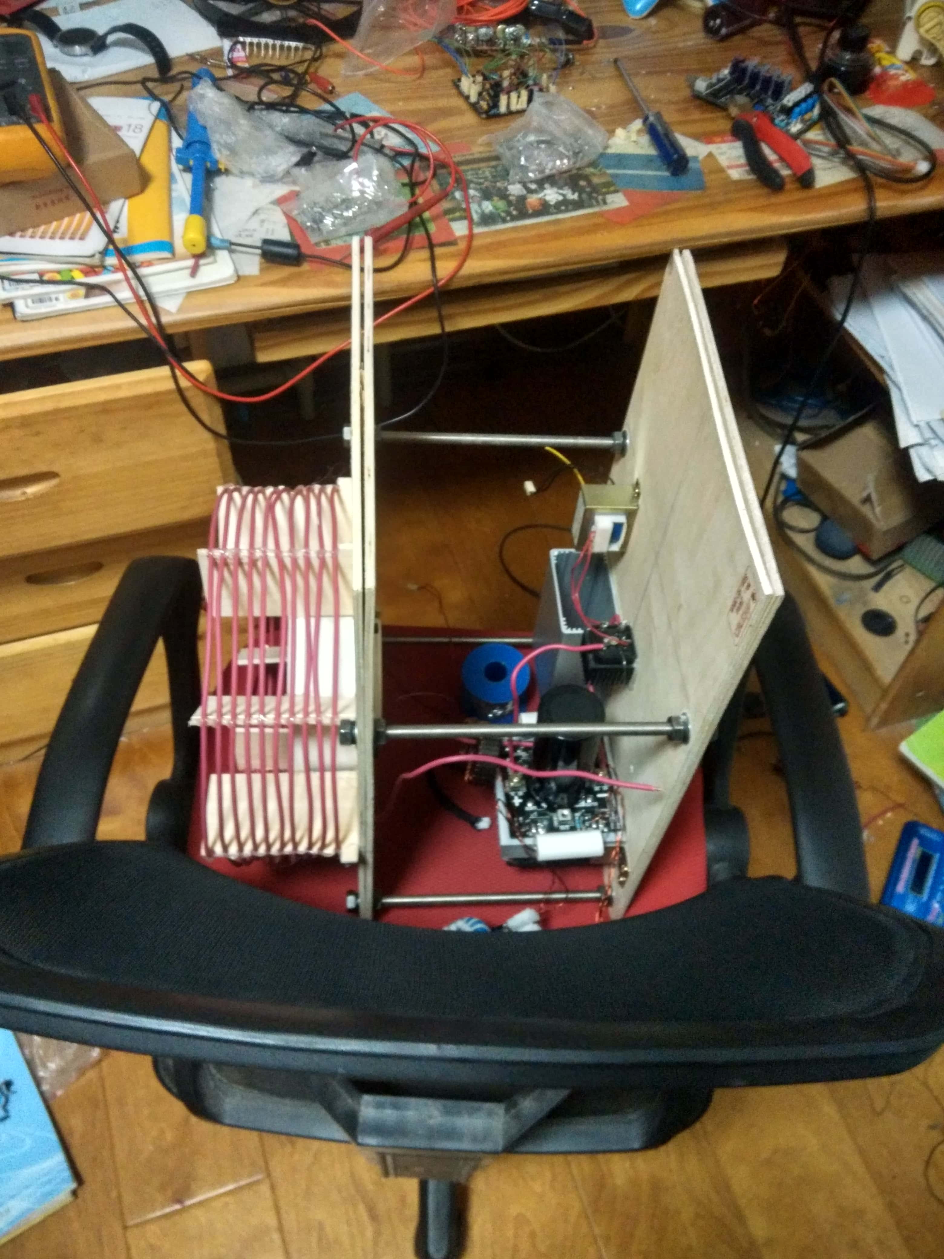
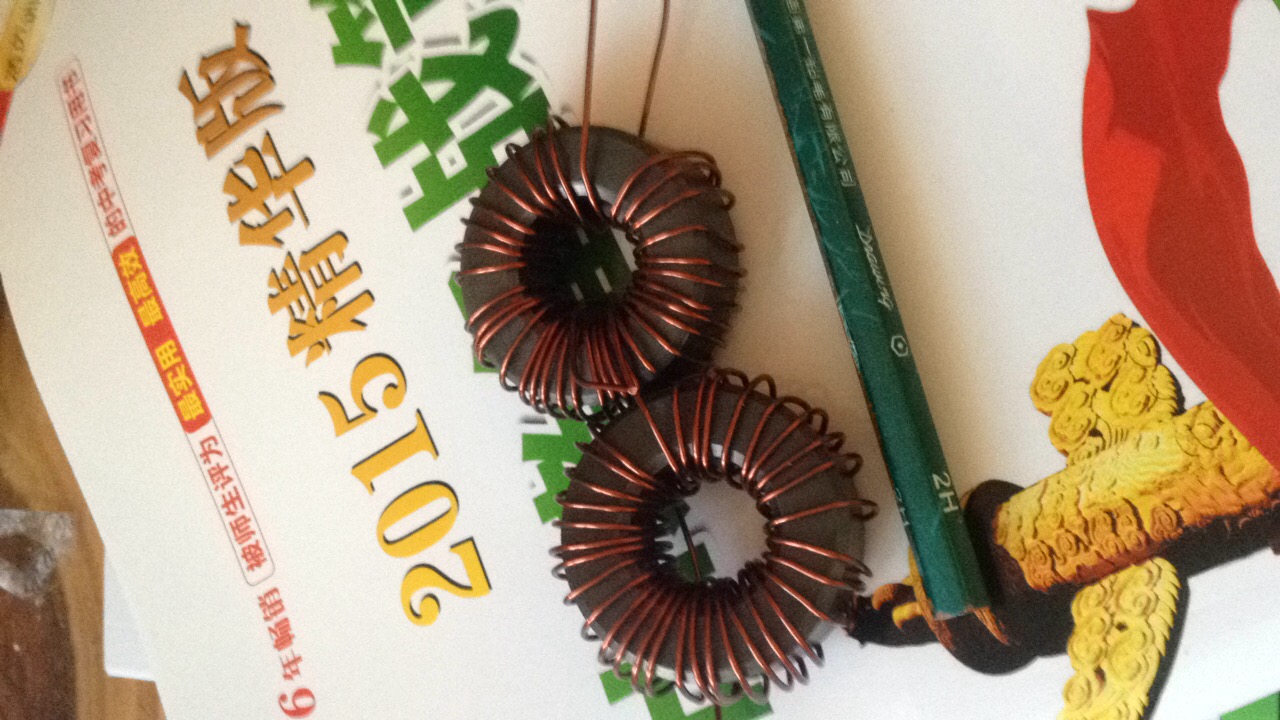
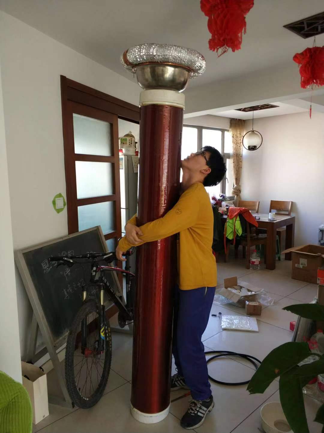
Finally, I got the whole device and I decided to test in my home. I have made a total of two coils based on different calculation parameters. My mom and dad helped me with the winding.
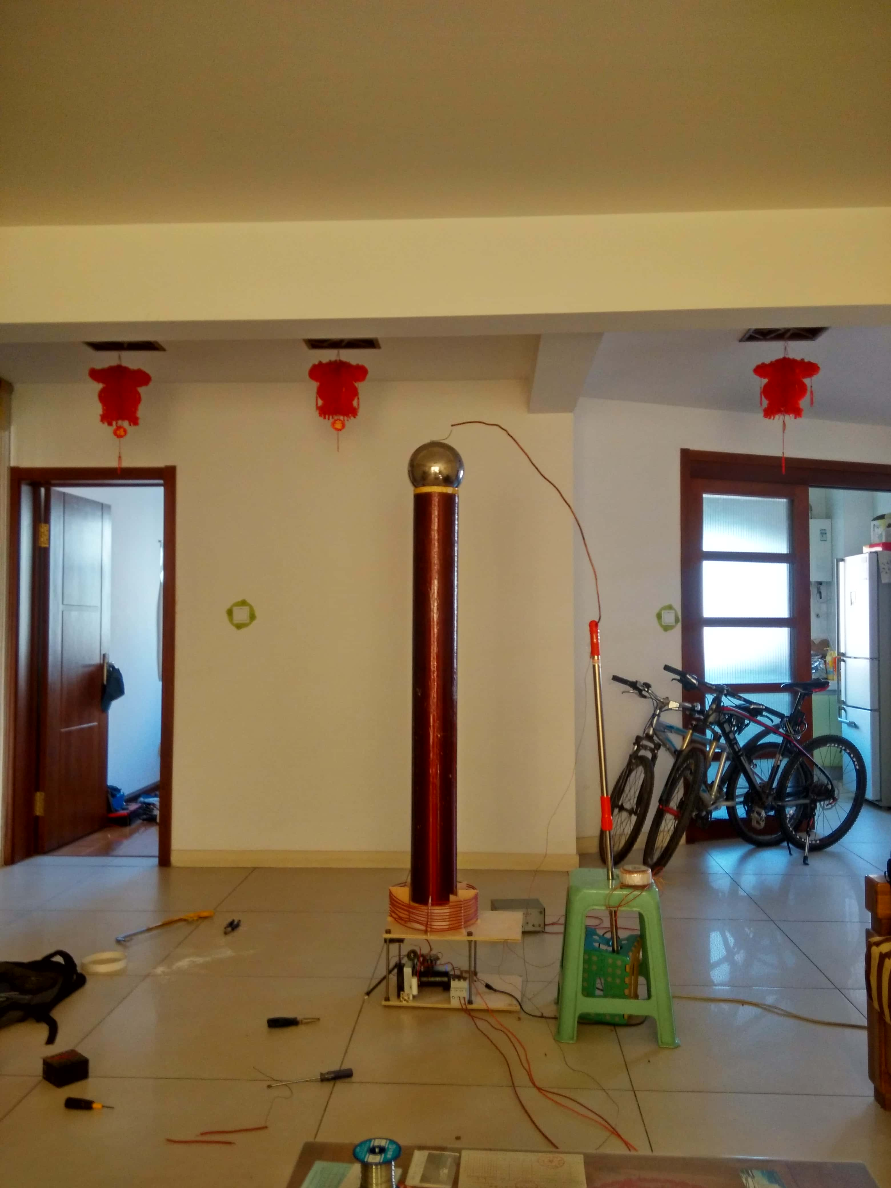
Actually, the result is not good. I have to change my solution and debug the whole system.
Gen 2
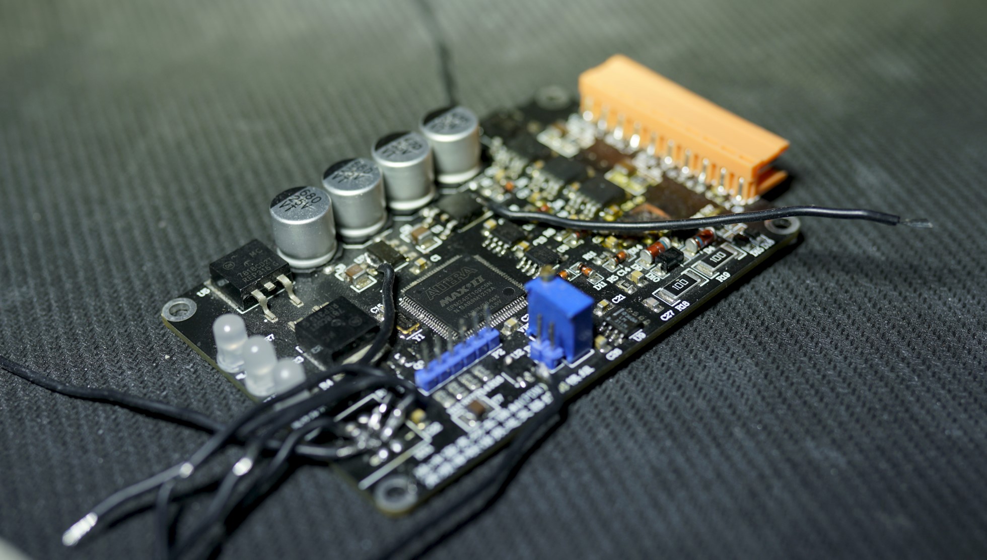
Following the prompt, I reached out to the CPLD. Here are the next gen. driver. The solution based on CPLD Altera MAX II, which integrated whole door circuit into one chip. The new GDT driver used P-N MOSFET FDD8424H to instead of IRFP540/9540 totem pole MOS amplifier.
At this time, I recalculated the resonance parameters, taking into account the conclusions of enthusiasts in other parts of the world.
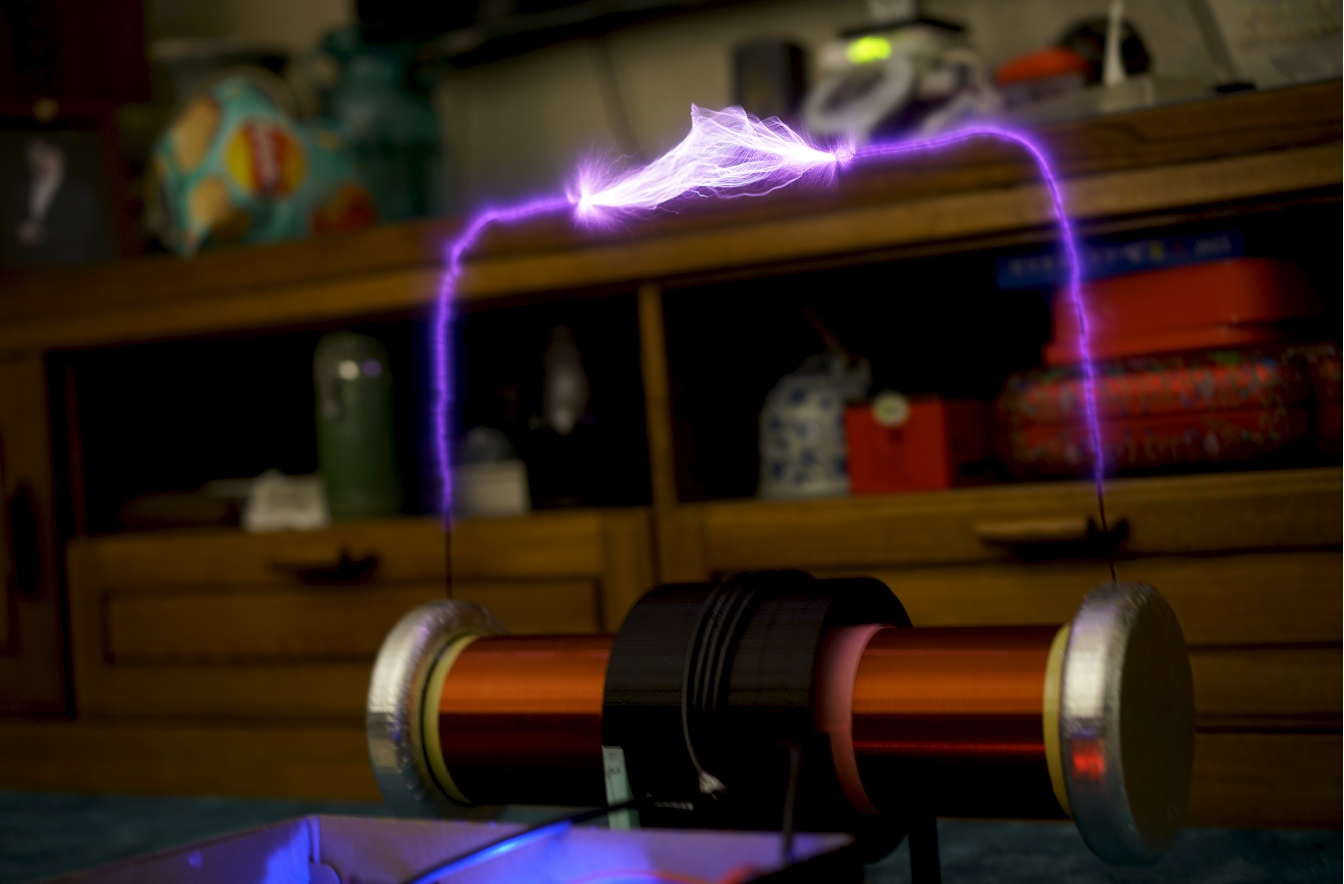
This time the result is very significant, at this point the resonant current has reached 100Amps according to the calculation, the IGBT is rated at 50Amps.
In order to be able to use the previous secondary coil and get better results, I set out to improve a new generation of inverters, this time with 5 IGBTs per arm in parallel.
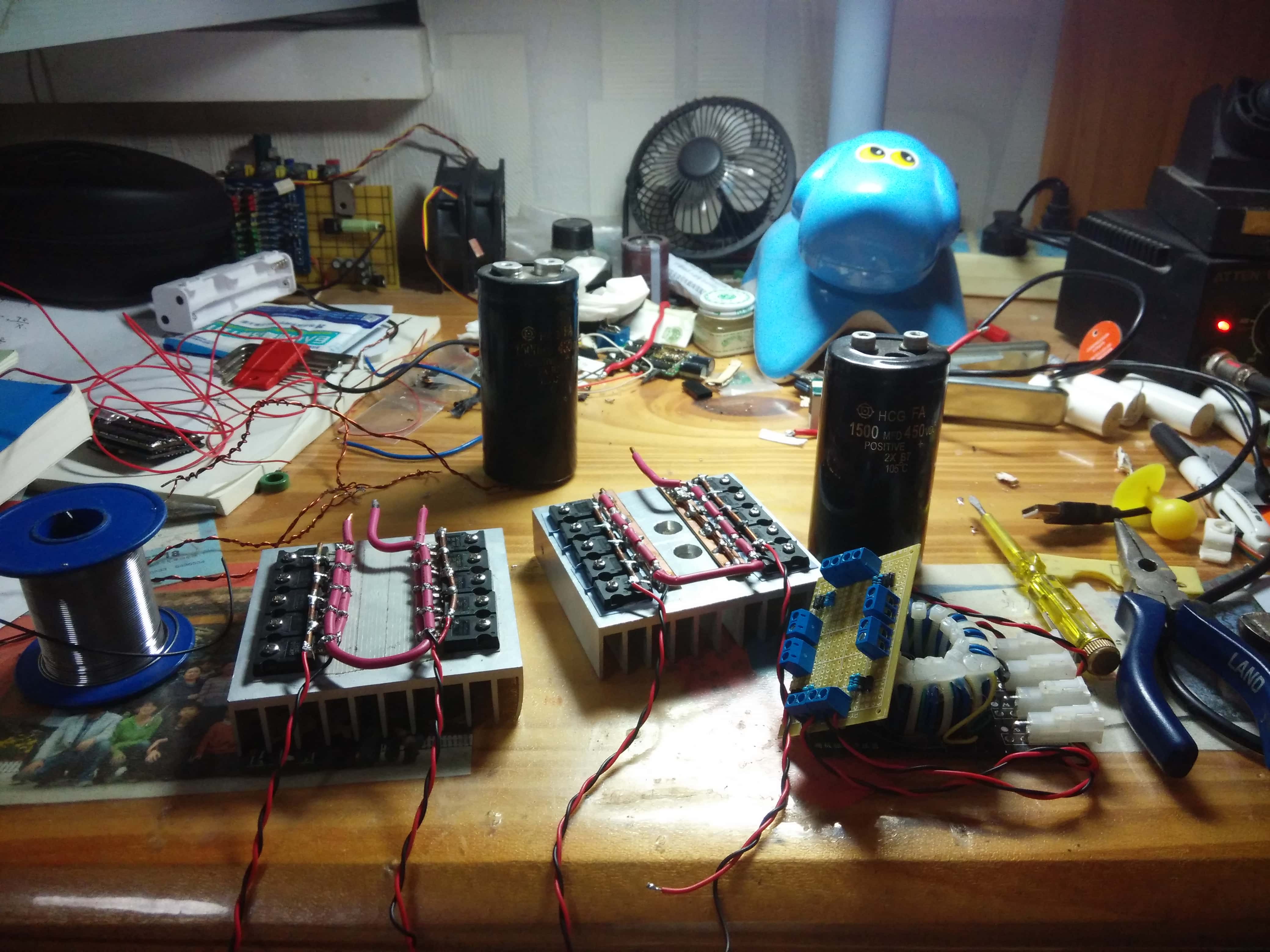
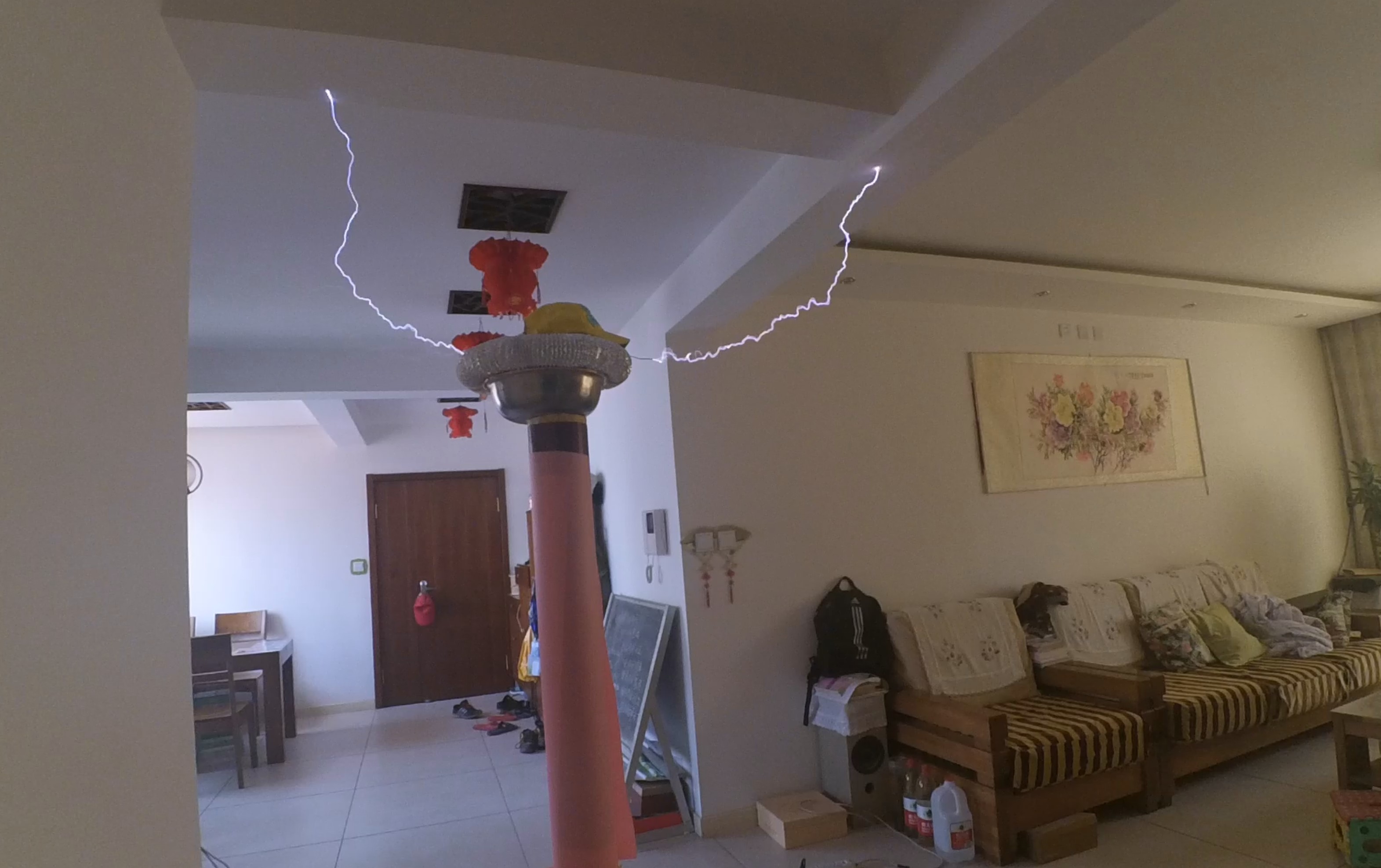
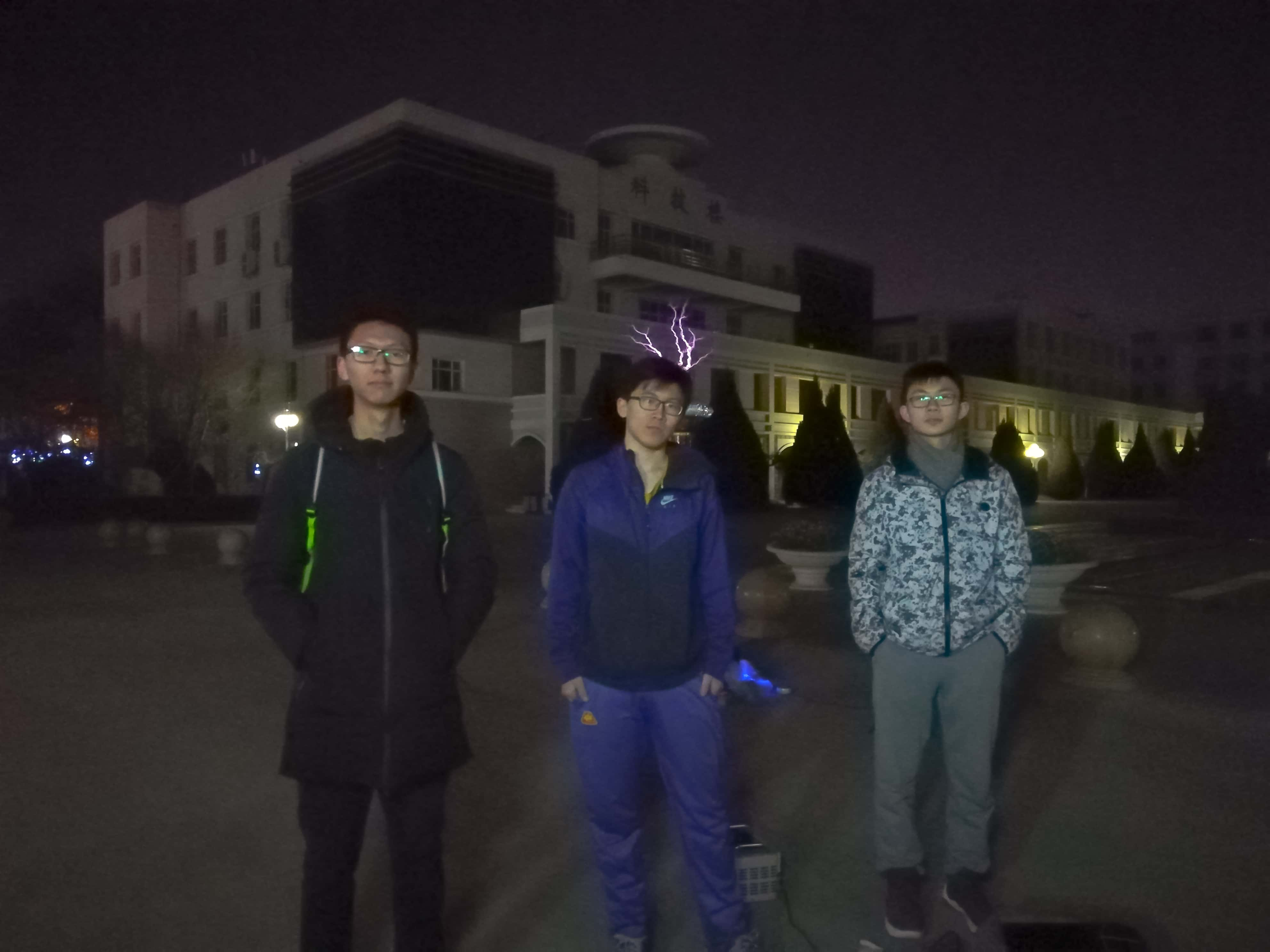
I tested the coil at my home and my high school.
Twisting
As time went by I came to the university, because of some trivial things, I couldn’t concentrate on doing higher power testing. So I switched to doing some optimization design.
Here are the new gen. driver based on CPLD Xilinx CoolRunner II. In this board, I tried to design some protect circuit and faster PWM Signal in CPLD. Such as a Phase shift circuit to protect the IGBT. Also, I add a isolated IGBT driver though Fiber to instead of Gate Driver Transformer(GDT).
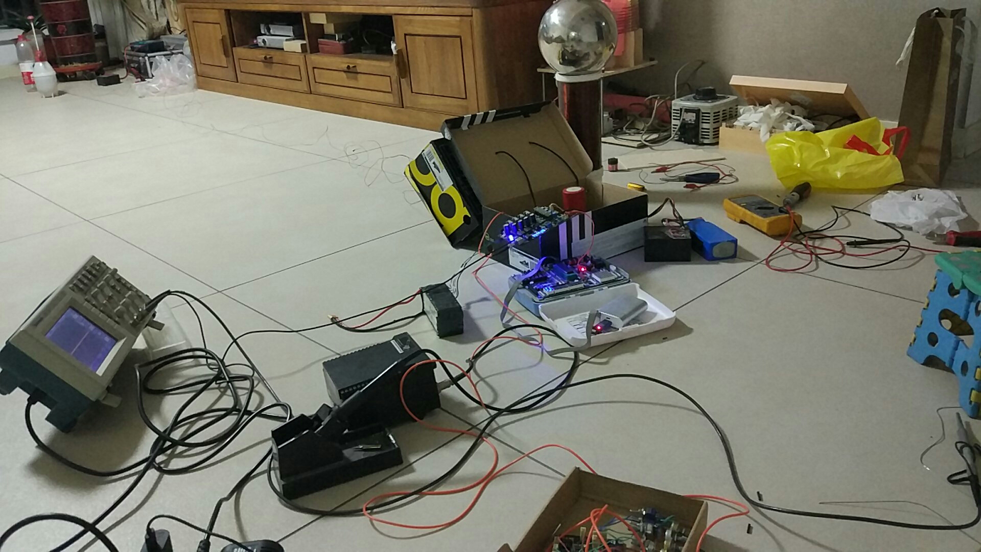
The new platform in my lab.
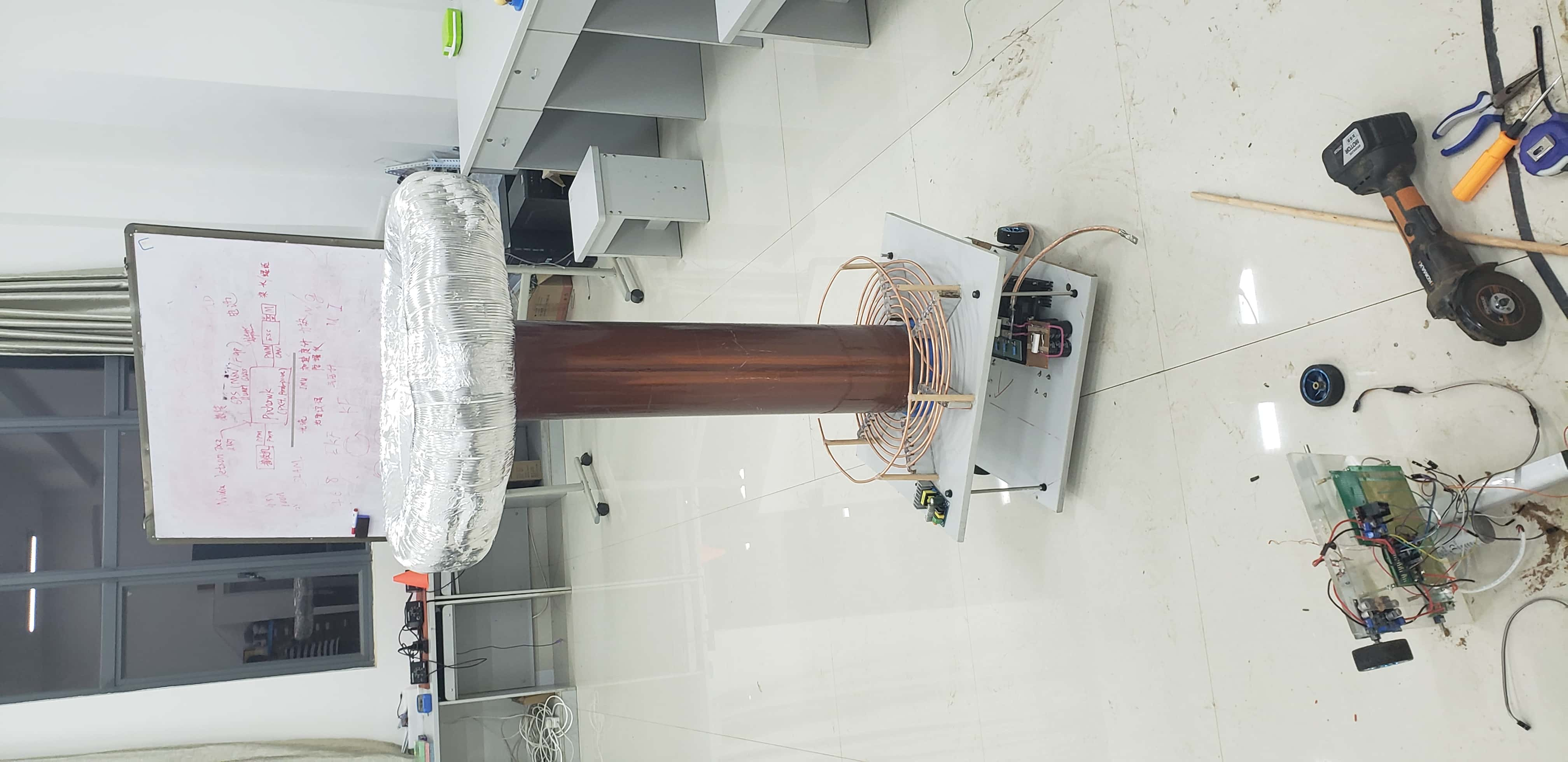
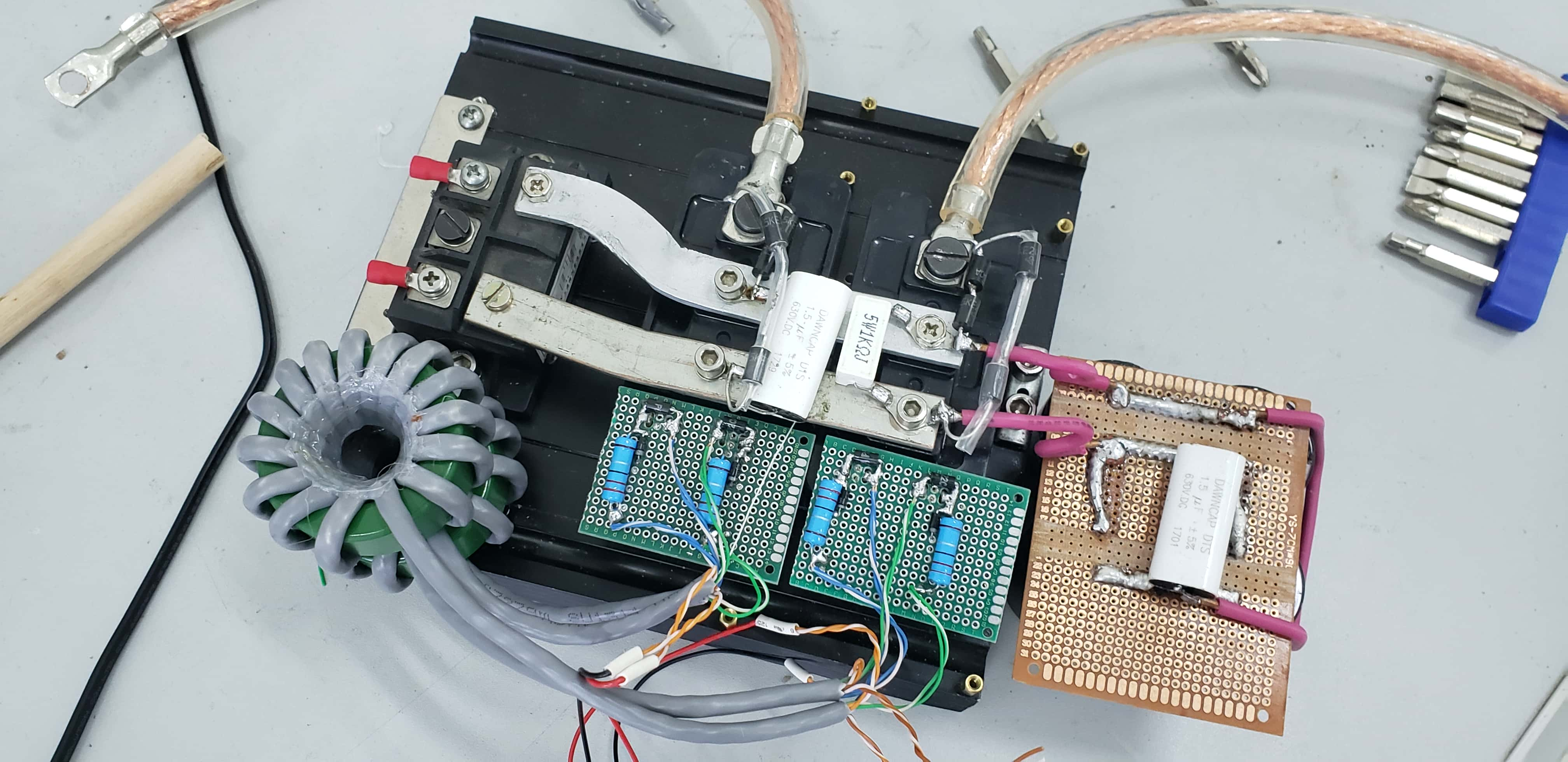
In this time, I tried to use the IGBT modules to build the full bridge inverter.
But It didn’t last long, as the program was quickly suspended by the school and terminated after I lobbied ineffectively.
Rebirth
Restart, new life……
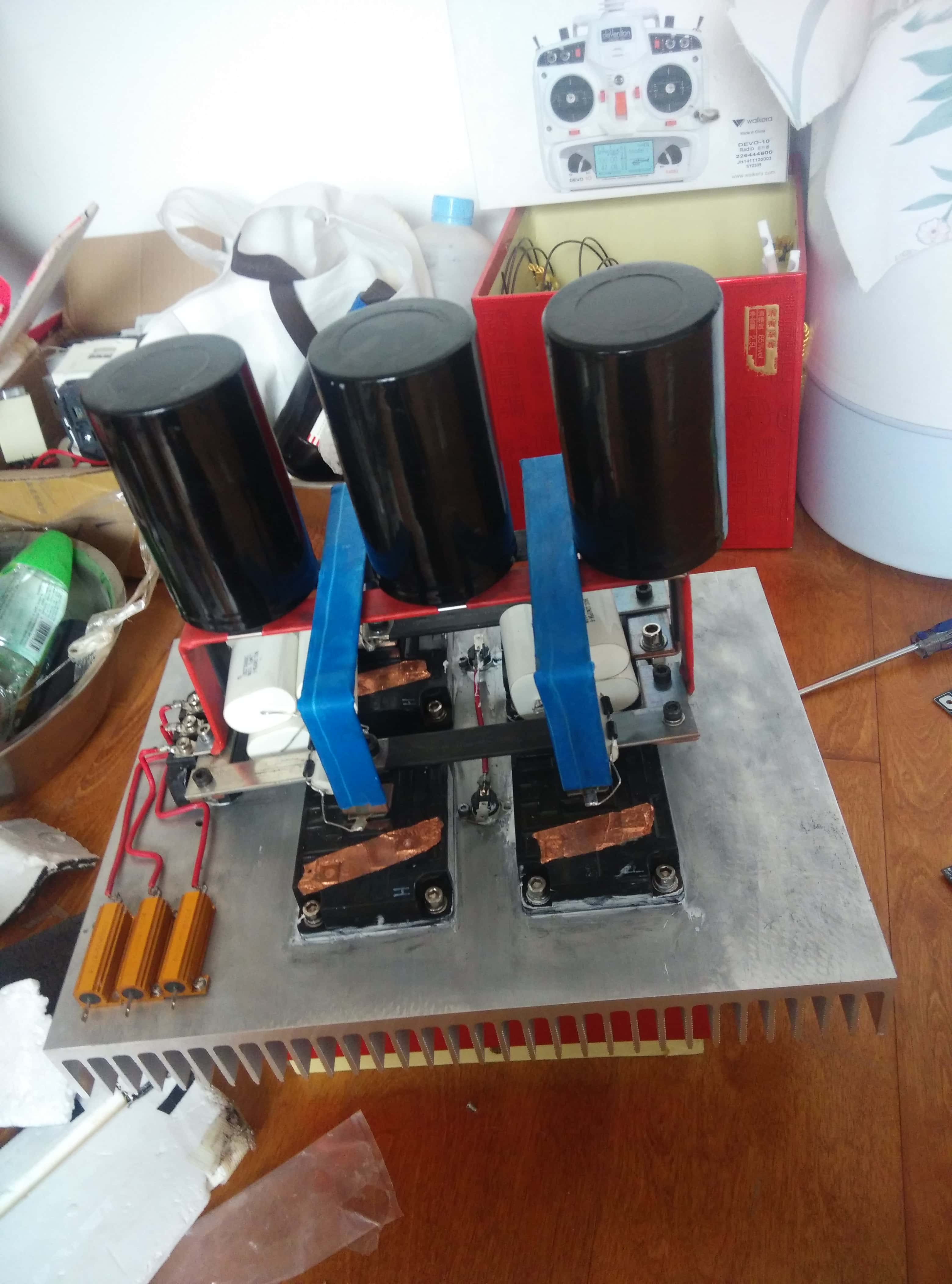
I still remember when I was in my third year of junior high school, my dad gave me 3,000 RMB to realize my dream, and in that year, I built an oversized IGBT inverter. But the lack of theoretical knowledge made me never successfully and safely drive up this big guy.
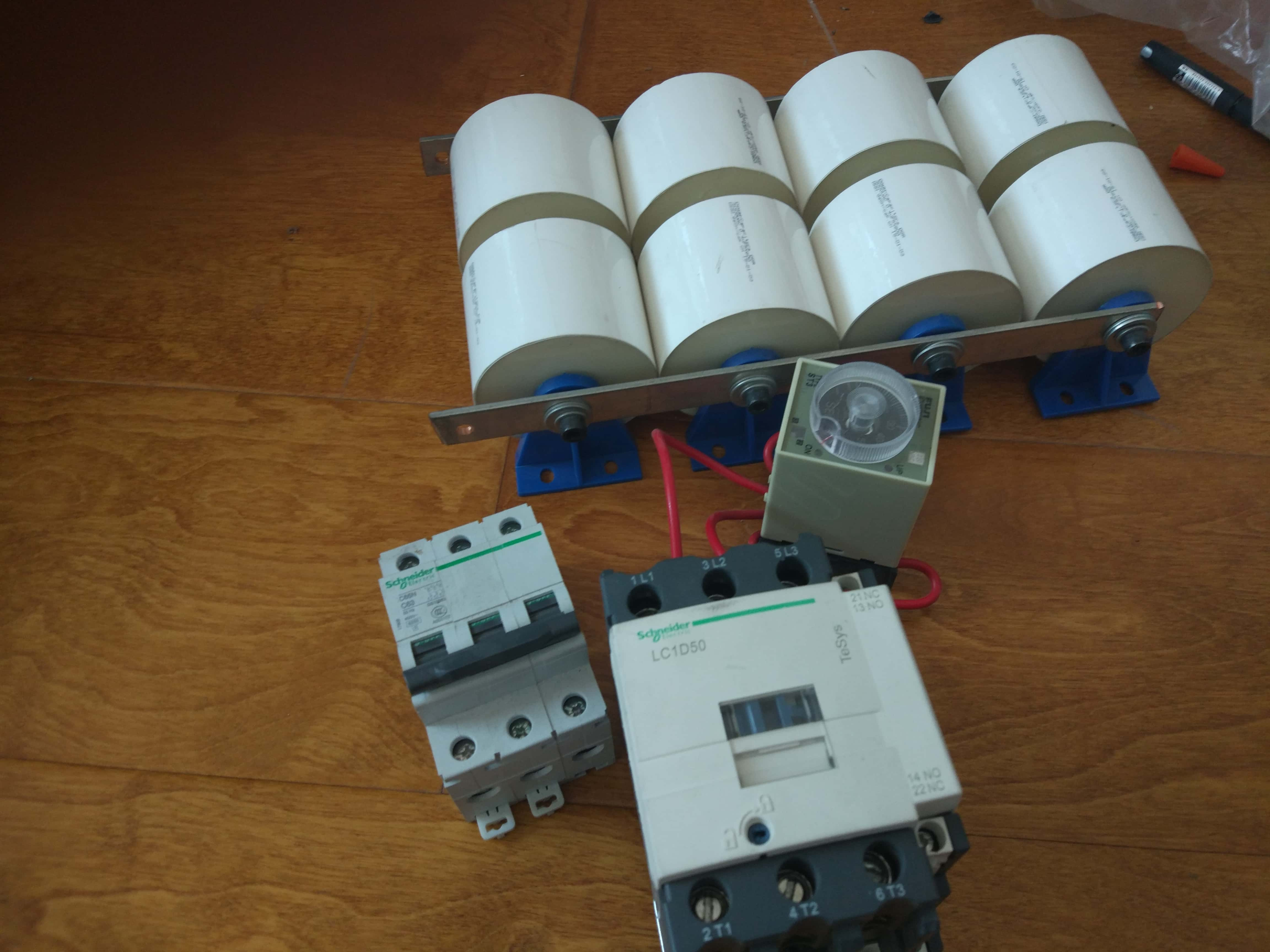
These are the resonant capacitors prepared at that time.
And this is the secondary coil that was prepared at the time.
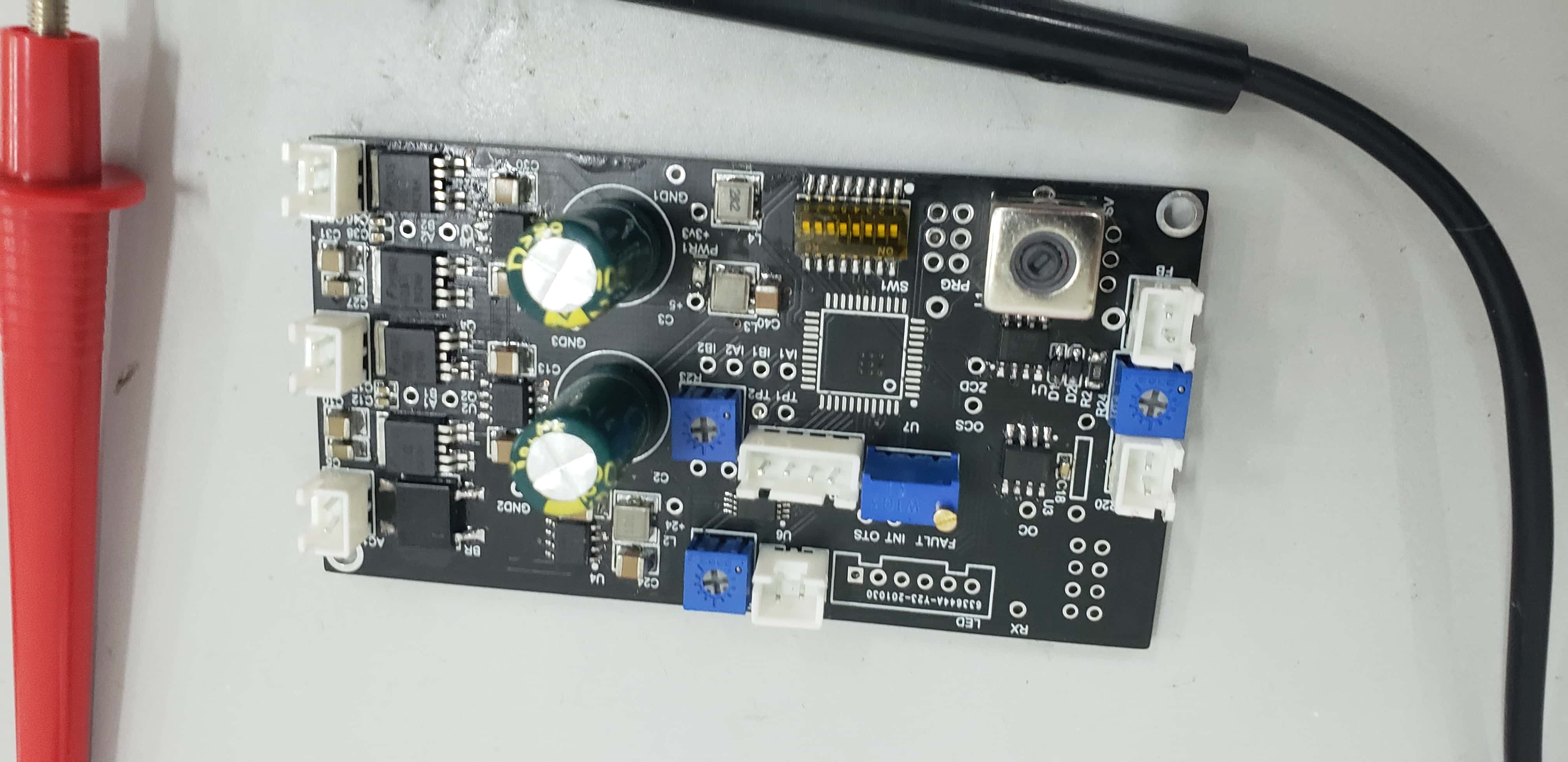
Before I did my graduation defense, I was reminded again of my childhood aspirations, so I redesigned the new driver circuit. The new driver based on Infineon Cypress PSoc, which integrated in FPGA, PGA and ARM.
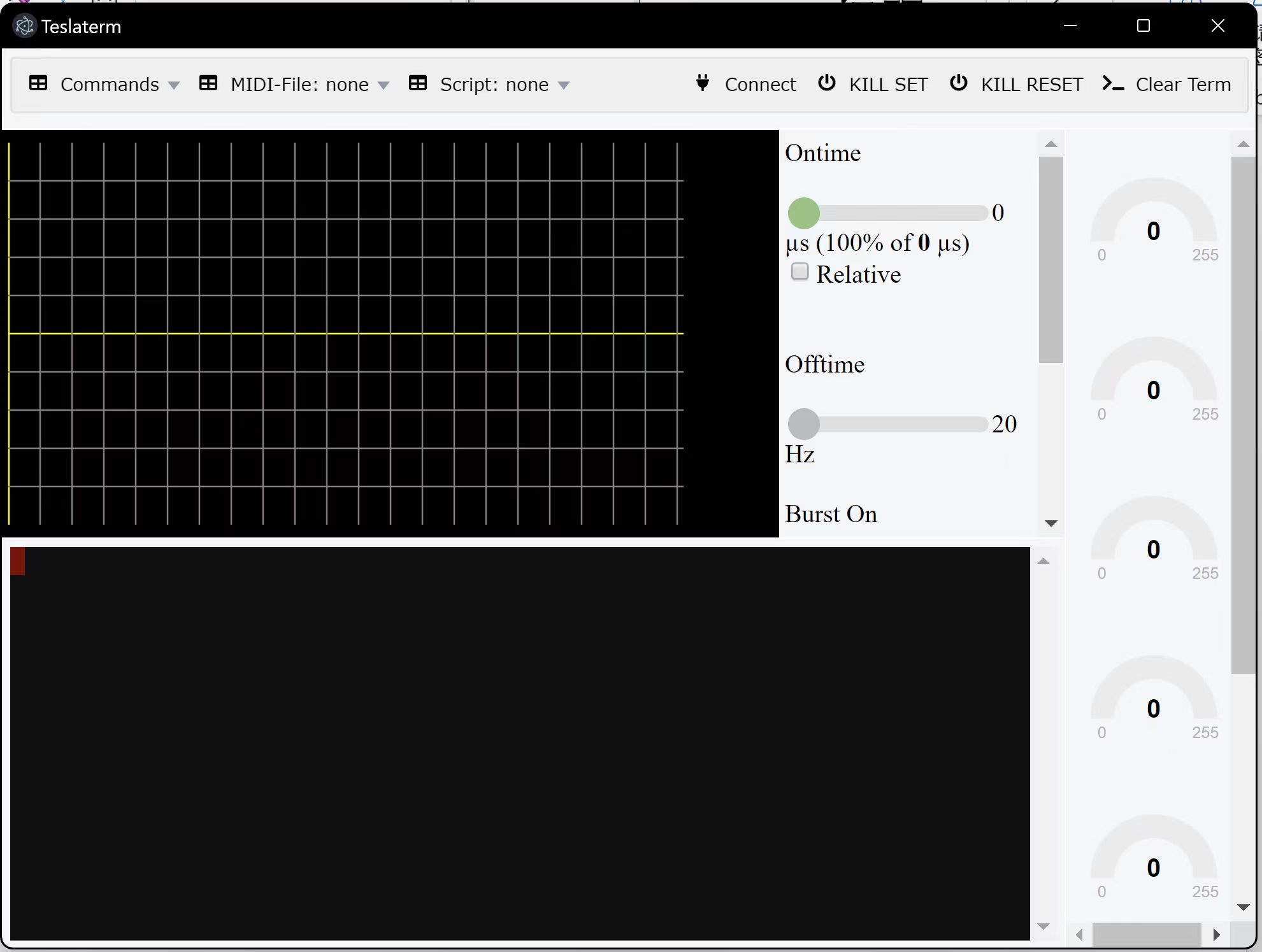
After that, I developed a GUI base on Node.js. It is a digital operate pannel with various sensor data.
I hope that someday I can actually finish and close this 10-year project!